
DIY Light Bezel for the Teeces v3.2 Logic Displays
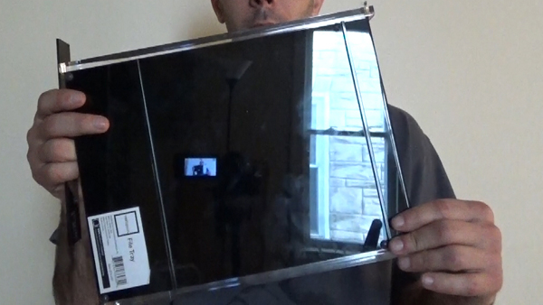
Thankfully, I was able to order a set from Joymonkey although I was all set up to make my own. I got a black acrylic file tray from Office Depot and found a 3mm drill bit (same OD as the LEDs) in a pack of multiple size drill bits which also came in very handy.
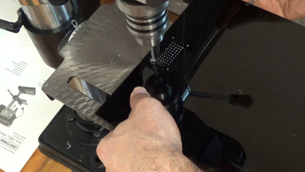
I used the Teeces FLD PCB as a template and a very small drill bit and stuck the drill bit into the negative LED terminals and gave the bit a couple of twists to create pilot holes. The holes don’t go all the way through. Just enough to make a divot in the acrylic.
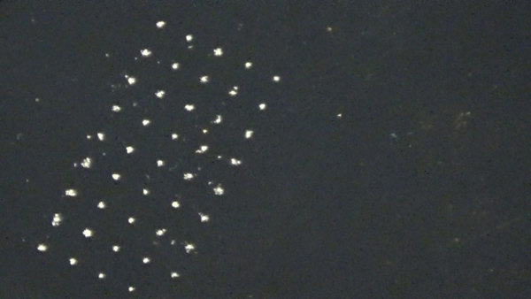
I did the same process again with a bit with a little bit bigger size, just without the PCB in place. You can feel the bit “click” into the pilot hole. A couple turns of that and the hole gets a bit bigger. I don’t go all the way through again so I create another larger divot than before.
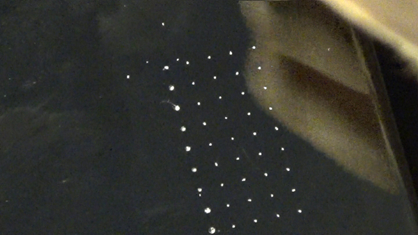
I keep doing this process each time stepping up the size of bit until I feel I have a decent size pilot that I can feel the 3mm bit seat properly into a divoted pilot hole. I used a paper template found from joymonkey somewhere that has the dimensions of the bezels with the outlined holes. This was lined up with the pilots to create the 4 screw holes.
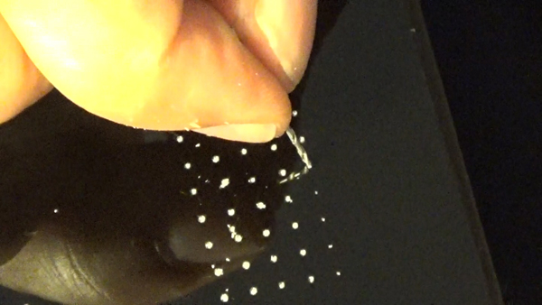
Than I used a drill press to make the hole go straight down. I would slowly bring the press down until you feel the bezel plate move into place as it takes the pilot hole into the bit. I continue driving down slow so it doesn’t pull up the acrylic as I am drilling.
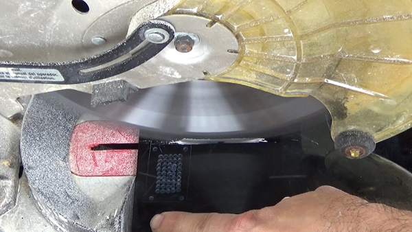
After all the holes are drilled out, I cut it with an electric miter saw.
Soldering the Arduino to the RFL on a Teeces V3.2
The lighting system works off of the Arduino Pro Mini from sparkfun.com and can be found HERE To get this to work, it needs to have a 5pin header soldered to it and then soldered to the PCB of the RFL. Once, the header is soldered, it would be a good idea to program a sketch into the Pro Mini. We need an FTDI, Mini USB programing cable, a driver for the FTDI, and the Arduino Program Software.