The R2D2 Wood Frame Templates

For this video, I made the templates out of MDF, however, it is better to make them out of at least 3/4″ plywood, if you plan to make another frame.  It would come in very handy.

The plans for this can be found in the  blueprints section of Astromech.net. I used the MHENKS plans and downloaded everything.  Even the CNC stuff since it contained instructions. Start out by tracing your lines on the MDF.  I suggest using the middle ring as a constant guide.  After doing this video, I discovered some easier ways which would be to use the middle ring for a majority of template creation as it is easier to make every piece identical off of the middle ring with the exception of the length of the slots.

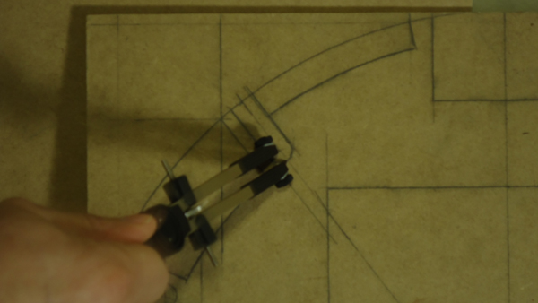
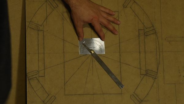
Get a good center point and find the zero angles first based on the Plans.

Protractor
Find Angles with a Protractor.


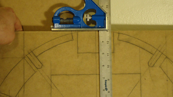
Draw out the other detail with your ruler.

Base plate
Marking the Top and Base plate.

The uprights should be created off of the long  upright with the most slots in it and the upright with only two slots.  My video is how I first made them, but it is easier with this method described.  This is why MDF is suggested since it is cheap and a good way to learn.

Marking uprights
Marking the uprights.

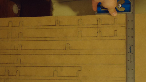
I used a compass to locate the postions of the end of the slots.  A dado blade can also be used, but be sure to follow the plans.

Radius cut
Radius cut for the slots.

Arduino Micro Controller for the Lights

Arduino

The Arduino can be used for many things when It comes to R2.  The lights is a good reason to use one, as it makes them flash and do all sorts of interesting things.  I have the Arduino Pro Mini and it only cost about $10.  This is extremely inexpensive for something that does so much for our little droid.

Arduino
Arduino and FTDI Breakout

You will see above is the Arduino Pro Mini and attached to that in red is the FTDI Break out, used for uploading a sketch to  the Arduino.  The sketch controls the lights and what they do.

The PSI Housing from PVC Coupler and Cutting Board

Cotton round in PSI

In order to make the PSI LEDS diffuse, we first need a housing to put them in.  The back PSI hole is larger than the front, so an 1.5 ID PVC coupler is used for both front and back. The size does not matter since the light will look the same regardless of the size of the coupler.

A bead of hot glue is first applied to the inside of a 1.5″ PVC Coupler.

Hot Glue in PVC Coupler
A bead of hot glue is applied to the inside of the 1.5″ ID PVC coupler.

The PSI Electronics is than dropped inside of the PVC and held in by the hot glue. Be careful when you place this in. The LEDs are placed downwards so make sure they do not get damaged by the inner edge of the coupling.

PSI into Coupler
The PSI Electronic LED is dropped into the coupler.

Two cotton rounds are placed inside of this to diffuse the light from the LEDs so they appear as one color and not separate bulbs.

Cotton round in PSI
Two cotton rounds placed inside the PSI Housing to diffuse the light.

Another bead of hot glue is placed on the top of the PVC housing where the cotton rounds sit. Place the cutting board circle on the glue and hold until glue sets.

Cutting Board on Coupler
Putting the Cutting Board circle onto the Coupler.

Hook the PSI up to the electronics to see how it looks!